- -- - - - - - - - - - - - - - - - - -
![]()
![]()
![]()
![]()
![]()
![]()
![]()
![]()
HW2036
Heathkit HW-2036 2 meter FM transceiver $1139.76
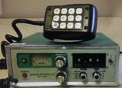
Year ~1977
Orig Price $269.00 (1977)
has the same buying power as $1139.76 (2018)
The Heathkit HW-2036 2 meter FM transceiver
covering 143.5-148.5 MHz with 10 watts.
The mic is hard-wired to the radio.
HWA-2036-3 power supply.
C416
adjust variable capacitor in VCO
until you get 2.2 volts on pin TP401 on synthesizer board.
Change C403 from .001 uF to 100 pF PN 21-75.
Remove the red wire and one lead of C2
.001 uF from point S.
Save the two ferrite beads from the lead of C2.
- Remove C2 and discard.
- Solder PCB pins B, L and N to the foil on the TOP side of the Transmitter board
- Splice the 2-1/2" red stranded wire onto the red wire
that was removed from point S.
Place sleeving over the splice.
- Connect the red wire to the OUT PCB pin.
Wrap the end of the wire around the top of the pin and solder.
Power Amplifier Board
- Prepare the #8 solder lug PN 259-24
(At 9/16" bend the eyelet end of the solder lug at a 90 deg angle.
Then cut off the end 1/2" from the bend.
- Mount the #8 solder lug and the #6 solder lug at point X,
The #8 solder lug is shown connected to the chassis with following sequence:
washer, #8 lug, #6 lug, nut.
The bent 'foot' of #8 is then soldered to the chassis.
- Solder the #8 solder lug to the chassis.
- Remove the shield lead of the coax cable
at point B on the Power Amplifier board.
Then solder this shield lead to the #6 solder lug at point X.
NOTE: When checking receiver spur levels,
a 50 ohm impedance must be connected to the antenna input jack.
No VCO Lock (Temperature Related)
QA has looked into this problem
and has determined that NPC or NP devices
should NOT be used for Q501, Q503 or Q401.
All other manufacturers of Part # 417-801's are acceptable replacements.
Diode VD-502, on the VCO circuit board,
should be an MV-2110 PN 56-640
check R302 on the Power Amplifier circuit board.
This resistor should be a 100 K ohm, 5 % PN 6-104-12, instead of a 10 %
VCO coil, blue PN 49-1855
C509; 22 pF capacitor PN 20-99
C513; 125 pF capacitor PN 20-177
R447 820 Ohm 470
R445 2200 Ohm 6800
C403 100 pF ceramic .001
Low Power Output
After the unit has been operating for a period of time,
L106 and L107 may not tune properly
and there will be low RF voltage at T1,
along with low power output.
The center conducter of J102 on the transmitter circuit board
may be cutting the insulator paper below the circuit board (on the chassis)
thus shorting the RF to ground.
If the lower washers on the board mounting studs are missing,
the board will rest too close to the chassis,
which causes the jack to come in contact with the chassis and insulator paper,
eventually shorting to the chassis.
Be sure the lockwashers are properly installed and if need be,
the center lug of J102 may be trimmed slightly
to provide additional clearance.
Synthesizer Light Will Not Go Out
If the voltage at TP401 has very limited range as L501 is adjusted,
and the synthesizer light will not go out even when TP401 is at 2.2 volts,
check C416, a 2.2 uF tantalum capacitor PN 25-221 for being shorted.
---
Reduce Receiver Spurs and Reference Tone in Transmit
The following changes are recommended to reduce receiver spurs and objectionable levels of 833 Hz reference tone in transmit signal.
You may not notice a significant reduction in the reference tone level if it is already low.
The "mod" will reduce the objectionable levels approximately 10 dB.
Parts Required: 1 ea #8 solder lug PN 2959-24
1 ea #6 solder lug PN 259-1
1 ea 100 pF capacitor PN 21-75
2-1/2" Small red stranded wire PN 344-90 3/4" Small sleeving PN 346-1
Transmitter Board:
- Change C403 from .001 uF to 100 pF PN 21-75.
- Remove the red wire and one lead of C2 .001 uF from point S.
Save the two ferrite beads from the lead of C2.
- Remove C2 and discard.
- Solder PCB pins B, L and N to the foil on the TOP side of the Transmitter board.
- Splice the 2-1/2" red stranded wire onto the red wire that was removed from point S.
Place sleeving over the splice.
- Connect the red wire to the OUT PCB pin.
Wrap the end of the wire around the top of the pin and solder.
Power Amplifier Board
- Prepare the #8 solder lug PN 259-24
(At 9/16" bend the eyelet end of the solder lug at a 90 deg angle.
Then cut off the end 1/2" from the bend.
- Mount the #8 solder lug and the #6 solder lug at point X,
The #8 solder lug is shown connected to the chassis with following sequence: washer, #8 lug, #6 lug, nut.
The bent 'foot' of #8 is then soldered to the chassis.
- Solder the #8 solder lug to the chassis.
- Remove the shield lead of the coax cable at point B on the Power Amplifier board.
Then solder this shield lead to the #6 solder lug at point X.
NOTE: When checking receiver spur levels, a 50 ohm impedance must be connected to the antenna input jack.
Receiver Spurs On Repeater Frequencies
A number of receier spurs are present in the HW-2036 and HW-2036A.
When the 10 MHz and 21.55 MHz oscillators are correctly set per the manual,
several of these spurs will occur on standard repeater channels, i.e., 147 MHz.
These spurs may be moved off channel by adjusting the 10 MHz oscillator high or low by some [change of] f,
and compsensating at the center of the band by readjusting the offset oscillators (receiver and transmit).
The spurs will move approximately 1500 Hz for every 100 Hz [change of] f,
and in the same direction as [change of] f.
For example, if the 10 MHz oscillator is set 500 Hz high,
the spur at 147 MHz will move up to 147.0075 MHz.
The offset oscillators must be adjusted in the opposite direction by 0.1 [change of] f for the HW-2036A, or by 0.117 [change of] f for the HW-2036.
(The offset oscillator does not affect spur frequencies.)
The price to be paid is a frequency error,
which will be maximum at the band edges.
This maximum error will be 1/5 [change of] f in the HW-2036A,
and 1/10 [change of] f in the HW-2036.
For example, if [change of] f = 1 kHz,
maximum error = 200 Hz in the HW-2036A, 100 Hz in the HW-2036
This is less than 0.00015% or 1/10 of the stability specification,
and should be an acceptable trade-off to a customer bothered by a spur.
The procedure is as follows:
1. Tune to the offending spur.
2. With dummy load attached,
adjust the 10 MHz oscillator
just enough to drop the spur to an acceptable level.
3. Set switches to center of band.
4. Adjust offsets by following one of the procedures in the manual.
5. Check to see that no spurs have moved onto other desired channels.
--